 June Power
June Power
June Power
Fast response is a practical measure of power regulation quality. A supply may hold its target voltage during steady operation, yet react poorly when a motor starts or a digital load changes suddenly. A brief 200-millivolt dip can reset sensitive equipment, increase ripple, or expose weaknesses in the control loop. Engineers therefore need more than attractive simulation results. They need repeatable measurements from real hardware.
This guide presents ten proven ways to Improve Response Speed of Power Regulation Systems. The methods cover sensing, compensation, switching frequency, gate-drive performance, current limits, and thermal control. Each area affects how quickly a regulator detects disturbance and restores stability. An oscilloscope, electronic load, and carefully placed probes can reveal details that firmware logs often miss. Probe ground loops can mislead results. Small layout changes matter.
Faster is not always better.
Aggressive control gains may shorten recovery time, but they can also create ringing, overshoot, or unstable operation. Practical design requires a balance between speed, efficiency, noise, and component stress. Load-step testing at different currents and temperatures provides stronger evidence than one laboratory trace. Designers should record settling time, peak deviation, recovery shape, and switching behavior. Some improvements may appear obvious but deliver little benefit after integration. That is worth questioning. Reliable power systems grow from measured evidence, cautious tuning, and honest review of unexpected results.
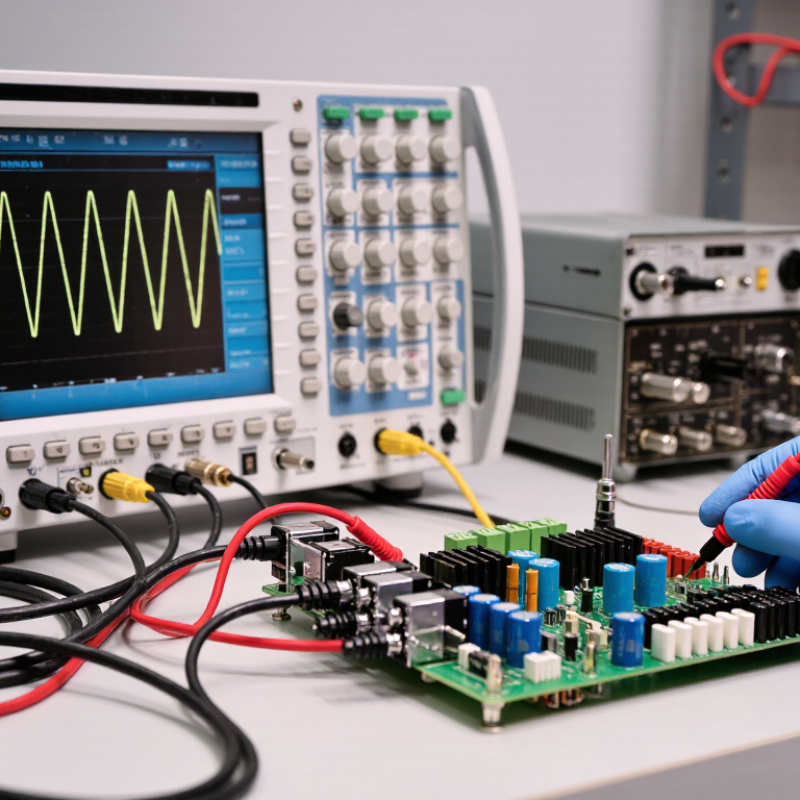
Response speed describes how quickly a power regulation system reacts when its input, output, or load changes. It is not simply the time required to reach a target voltage. Engineers also examine rise time, settling time, overshoot, and recovery after a sudden load step.
A fast response usually depends on accurate sensing, suitable control-loop bandwidth, and low parasitic resistance. During testing, I apply a controlled load step and record the output with a properly compensated probe. Numbers reveal behavior. A waveform that rises quickly may still produce excessive ringing or voltage overshoot. That stress can affect sensitive circuits and reduce operating reliability. The load is never polite.
In practical designs, response speed must match the system’s real operating conditions. A converter that performs well at room temperature may respond differently after heating, aging, or reaching its current limit. I once focused too heavily on rise time and overlooked a long settling tail. The result looked impressive in a short measurement, but the output remained unstable longer than expected. That mistake showed why engineers should compare several load levels, input voltages, and temperatures. Filtering can reduce measurement noise, although excessive filtering may hide genuine instability. Control settings should be adjusted gradually, with protective limits enabled during each test. A repeatable test record makes later decisions more reliable.
| No. | Improvement Method | Primary Response Metric | Typical Effect on Response Speed | How to Apply It | Main Trade-Off or Limitation |
|---|---|---|---|---|---|
| 1 | Increase Control-Loop Bandwidth | Closed-loop bandwidth and settling time | A higher practical bandwidth generally shortens the time required to correct voltage or current disturbances. | Tune the compensator using measured plant characteristics, phase margin, gain margin, and load-transient tests. Maintain adequate stability margin rather than maximizing gain alone. | Excessive bandwidth can amplify noise, reduce phase margin, and cause oscillation. |
| 2 | Use Faster Sampling and Control Computation | Sampling period and computation delay | Reducing sensing and calculation delay improves the controller’s ability to react during fast load or input changes. | Use a sampling frequency appropriate to the switching frequency and control bandwidth. Optimize interrupt scheduling, arithmetic operations, and task priority. | Higher sampling rates increase processor load, memory traffic, and measurement-noise sensitivity. |
| 3 | Minimize Sensing and Signal-Path Delay | Sensor, filter, isolation, and communication delay | Lower delay improves phase margin and reduces the time between a physical disturbance and corrective action. | Place voltage and current sensors close to the controlled node, reduce unnecessary filtering stages, and use low-latency signal conditioning with properly selected cutoff frequencies. | Less filtering may allow more switching ripple and electromagnetic interference into the feedback signal. |
| 4 | Add Feedforward Control | Disturbance-to-control delay | Feedforward can respond to measurable input-voltage or load-related disturbances before the feedback loop detects the resulting output error. | Measure the relevant disturbance and calculate a predicted control command. Combine feedforward with feedback so modeling errors are corrected safely. | Performance depends on model accuracy, sensor quality, and proper scaling across operating conditions. |
| 5 | Use an Inner Current-Control Loop | Current-loop bandwidth and inductor-current response | A fast inner current loop can regulate energy flow quickly while a slower outer voltage loop manages the output setpoint. | Use cascaded control with the current loop designed significantly faster than the voltage loop. Include current limiting and accurate current sensing. | The added loop increases design complexity and requires careful bandwidth separation and interaction analysis. |
| 6 | Optimize Output-Capacitor Selection and Layout | Equivalent series resistance, capacitance, and parasitic inductance | Appropriate capacitance and low-parasitic connections reduce immediate voltage deviation during a load step and help the regulator recover smoothly. | Select capacitance, ripple-current rating, ESR, and ESL according to the converter topology and transient requirement. Place capacitors close to high-current paths and the regulated node. | More capacitance can increase size, inrush current, cost, and control-loop compensation requirements. |
| 7 | Improve Power-Stage Switching Performance | Switching frequency, transition time, and energy-transfer delay | A faster power stage can transfer corrective energy more frequently, potentially reducing transient recovery time. | Select suitable switching frequency, gate-drive strength, inductance, dead time, and semiconductor operating margins. Validate switching waveforms and thermal behavior. | Higher switching speed can increase switching losses, electromagnetic interference, ringing, and thermal stress. |
| 8 | Improve PCB Current Paths and Grounding | Parasitic resistance, inductance, and feedback-noise level | Lower parasitics reduce voltage error, ringing, and measurement distortion, allowing the controller to respond to the actual output condition more accurately. | Use short, wide high-current traces; minimize switching-loop area; separate power and sensitive signal returns; and use Kelvin connections for critical measurements. | Layout optimization may require additional board area, routing constraints, and thermal design effort. |
| 9 | Use Adaptive or Gain-Scheduled Control | Performance across load, input, and operating-temperature ranges | The regulator can maintain faster and more consistent response when plant characteristics change with load current, input voltage, or temperature. | Adjust control gains, compensation parameters, or operating modes using validated operating-region thresholds. Apply interpolation carefully to avoid abrupt control changes. | More software and verification are required, and poorly defined transitions can introduce instability or output disturbances. |
| 10 | Optimize Protection and Operating-Mode Transitions | Protection blanking time, restart delay, and mode-transition latency | Well-designed protection and transitions prevent unnecessary delays during start-up, current limiting, light-load operation, and recovery from temporary faults. | Review soft-start ramps, current-limit response, fault-retry timing, pulse skipping, discontinuous-conduction transitions, and mode-change thresholds using worst-case transient tests. | Reducing delays without proper validation can compromise fault protection, component safety, and system reliability. |
| Engineering note: Actual response speed depends on converter topology, control architecture, switching frequency, load profile, component tolerances, sensor bandwidth, layout, and stability margins. The methods above should be validated through load-step, line-step, startup, fault-recovery, and temperature-corner testing. | |||||
Delays may start in the sensor, before the controller reacts. A 2-millisecond filter can weaken a fast protection loop. Measure every stage directly.
Use synchronized voltage and current probes near the switching equipment. Record filtering, conversion, and communication time separately. Cable noise may cause unnecessary corrections.
Yes. Poor tuning can produce oscillation, overshoot, and extra thermal stress. A loop may react quickly but still regulate badly. Speed is not enough.
Record sampling time, computation time, and output-update delay independently. Compare the command waveform with the measured response. The difference can expose hidden delay.
Gate-driver delay, switching dead time, and thermal limits can slow practical response. Measure waveforms at the device terminals. The controller may be innocent.
Use dedicated measurement channels and short copper or fiber routes. Separate protection traffic from routine monitoring. Test during packet congestion, not only normal operation.
Timestamped events help align voltage changes, messages, decisions, and actuator movement. Poor synchronization can make a system appear faster or slower than reality. The test setup may deceive us.
Apply stepped loads and record voltage recovery and settling time. Use a calibrated analyzer, oscilloscope, thermal camera, and controller logs. Repeat tests under realistic loads.
Trend sensor drift, switching temperature, response time, and protection events. Inspect terminals for discoloration and check cooling airflow. Small details matter.
Field cables may add impedance, while loose connections create unexpected voltage drops. Probe placement and sampling rates can also mislead engineers. One impressive benchmark is not enough.
Improving the response speed of power regulation systems requires a complete understanding of how quickly a system detects changes, processes information, and adjusts its output. The process begins by identifying delays in sensors, controllers, power devices, and communication links. Careful analysis can reveal whether slow measurements, excessive filtering, inefficient code, switching limitations, or transmission interruptions are restricting performance.
To Improve Response Speed of Power Regulation Systems, engineers can refine control algorithms, reduce unnecessary calculations, optimize sampling and feedback settings, and coordinate hardware components more effectively. Faster communication paths, shorter signal routes, and properly selected power devices can further reduce system latency. Regular testing under changing loads and operating conditions is also essential for verifying stability and accuracy. Preventive maintenance, performance monitoring, and timely calibration help preserve high-speed regulation over time, ensuring that the system responds quickly without sacrificing reliability, safety, or control quality.
